In this post I intend to explain what is going on inside your keyboard, from the switches all the way to the operating system, where the data terminates. I hope to go into some detail about how custom controllers like Soarer's convertor and controller, HaaTa's KiiboHD and TMK (among others) work to communicate keypresses to your operating system through the USB-HID subsystem.
Keyboard Switches
Keyboard switches are a contentious and seemingly deep topic of discussion. Luckily for us, most of the contention is around preference and variations in feel. Most mechanical switches themselves work in nearly the same way. For an in-depth look at just about everything you need to know about switches, check out the excellent Introduction to Cherry MX mechanical switches. There are excellent animated gifs there like the one below. They explain the inner workings and physical properties of the feel of keyboard switches.
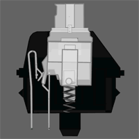
That gif is an image of a Cherry MX Clear switch, and it shows what is going on inside the switch. There are only really two components in the switch that matter for the actuation. In that image, the plastic part in between the folded metal piece on the left side of the image is of the switch is the actuator. The leaf is the moving metal bit which controls the contact and continouity of the current moving through the switch. When the actuator drops, the leaf of the switch touches the stem momentarialy and continuity is restored. This is communicated to the controller, which decides what to do about it. In most cases it emits a KeyPress event. When your finger leaves the switch and the actuator separates the leaf again, there is a KeyRelease event. There is a good wiki post on this on Deskauthority.
There is also the outstanding post on the WASD website which explains the differences in switches, mounting, and their actuation. You should breeze through that as well.
What is important to understand is that the switches themselves are just that. Momentary contact switches. Their objective is to momentarily allow the flow of current through a circuit using the actuator to connect the leaf and stem. The release of the button shold break that contact.
This is soley talking about mechnical keyboard switches, as there are many other ways to indicate this to a circuit. The articles on the deskthority wiki on Contact Mechanisim and Switch Terminology are good resources to read up on this topic.
Internal Wiring
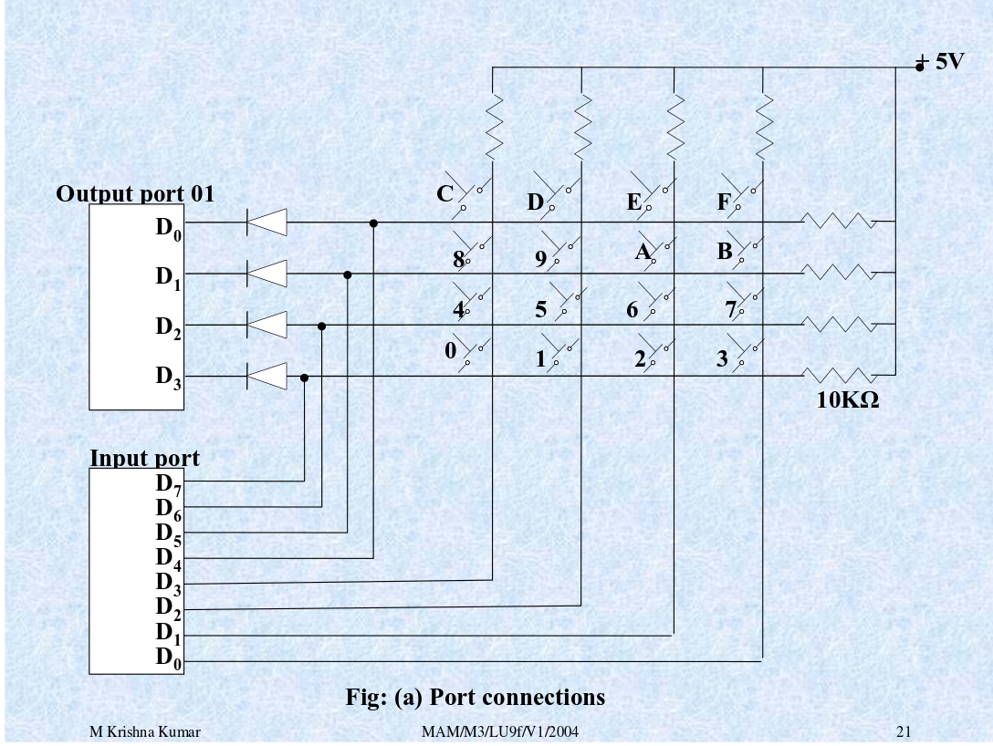
The switches in a keyboard are wired in a matrix configuration as shown below. This means in serial, one switch after the next, on the same bus as the previous. In the gif, the “A” key is pressed, as the switch is in the closed state, signaling to the microcontroller that the key has been pressed. There is a bit of knowledge one needs to have about muxing and diodes, and how they work together to fully understand how a one could have a controller with fewer pins than switches could accurately represent the states of all the switches, all the time.
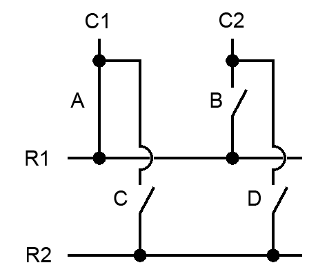
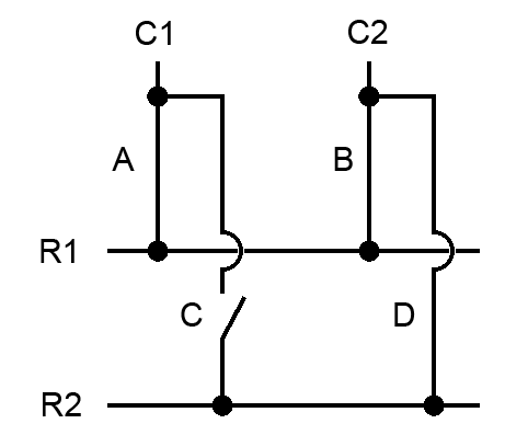
Let us have a look at our hypothetical diagram above, and pretend we have a keyboard with these four switches, [“A”, “B”, “C”, “D”]. If A, D and B are pressed at the same time, the entire circuit is complete, and despite not pressing it, the C switch goes hot. The diagram below illustrates that. The reason this happens is because the current is flowing in both directions when the circuit is complete on either side, due to the nature of it being wired in serial.
The purpose of a diode is to ensure that electrical current can only flow in one direction. A diode will block the current from flowing up the unintended leg of another simultenious or near simultenious keypress, as illustrated in the circuit below.
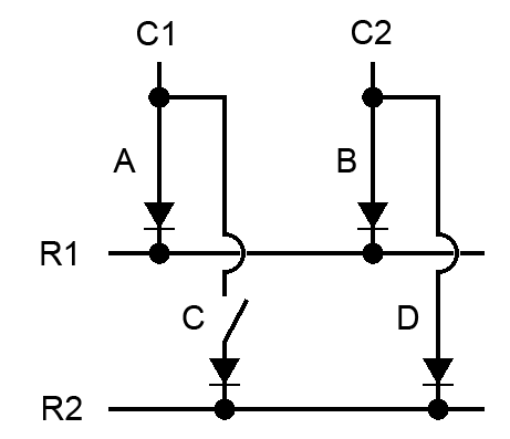
Mind you, these diagrams were made by Manyak on the overclockers.net forum. It is a great resource. RIP forums as the source of all the knowledge on the internet.
Keyboard Hardware and Internals
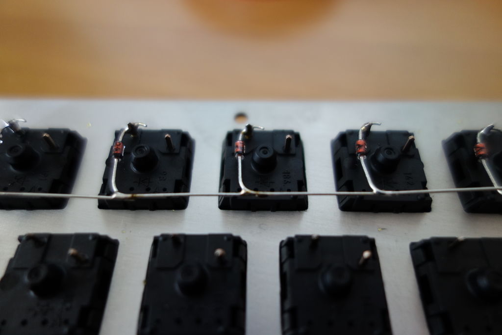
If the schematic in the previous part was not very helpful for understanding what is going on inside the keyboard, I found some excellent pictures from a custom keyboard build by a user named matt3o on the deskauthority forums. He took a lot of excellent photos while building his brownfox keyboard.
First, he wired the switches in rows, using diodes.
As you can see from further away, they are wired in serial and do not terminate anywhere yet.
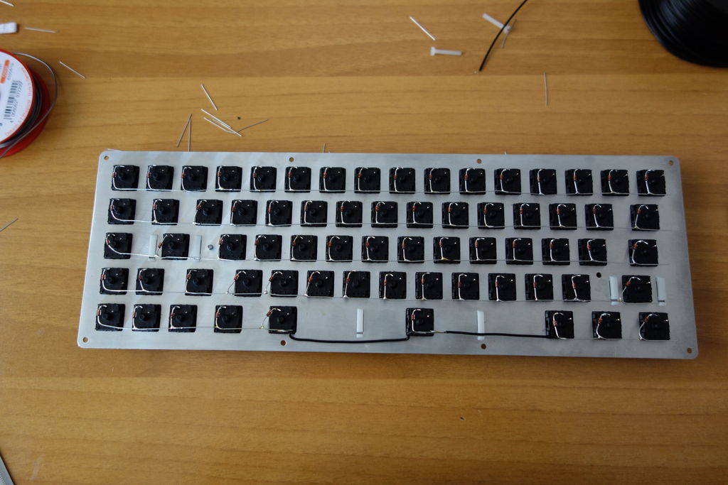
Next, the columns were wired up, also in serial. He used insulation to keep the vertical wires from touching the exposed wiring of the diode legs. He passed the wiring underneath to keep it neat and easily debuggable if something went wrong. This mirrors the illustration above.
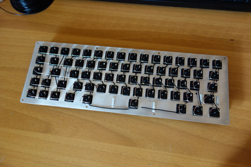
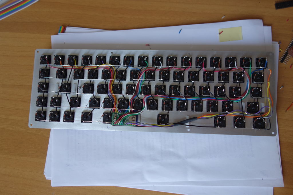
Lastly, he wired the individual rows and columns to to a microcontroller. In this case a Teensy 2.0, commonly used in keyboard projects because of its small size and the availability of good, open-source and battle tested firmware available for it. The high number of inputs and low power consumption are also key factors in this decision.
The microcontroller
Heading back inside the keyboard, we can think about the microcontroller in 3 discrete components:
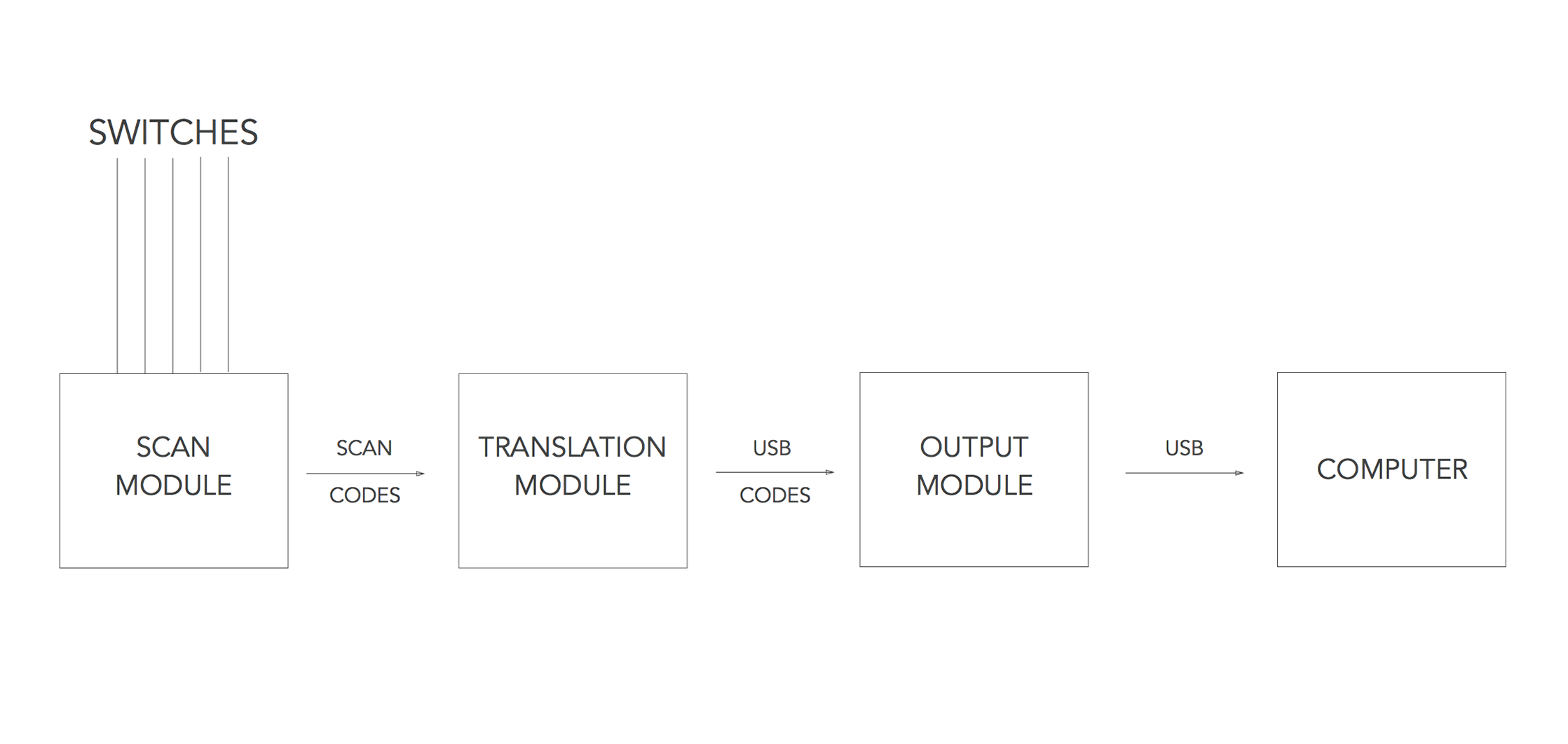
The scan module: This takes the state of the keys on the board and turns them into scancodes for the translation module to interpret. Most of the time, when customizing a keyboard in hardware, the layering and most of the configuration happens here.
The translation module: This module of code takes the scancodes and maps them to USB-HID output codes, or whatever sort of output you might want like midi or physical interfaces. USB-HID being the most likely for keyboards. This is can also be known as the macro module.
The output module: This sends signals to the device it is attached to over the protocol decided in the translation module, again most often USB, but in the cases of Soarer's convertor, it can output many different kinds of proprietary keyboard protocols.
The image is from the great Massdrop article by HaaTa (registration annoyingly required). I hope to go into a bit more detail about the specifics of how the firmware communicates with the HID subsystem, the kernel, your window manager, and eventually whatever application is using it.
What is USB-HID?
USB HID is the Human Interface Device standard used by USB to deal with interfaces devices.
The HID standard specifies a set of descriptors and protocols that the author of a device driver or any of software can choose what to do with. This gives a great level of flexibility in what HID can be used for. A simple example would be a two button mouse. Once a device negotiates with HID that it is a mouse, HID provides an interface that allows the mouse to specify a very limited number of variables as they come through the hardware to the HID. Namely the state of the two buttons, and the X and Y displacement. Driver authors and hardware manufacturers can extend this to other functionality your mouse probably has, like a scrollwheel and a third button, but HID takes care of the basic hardware to host communication.
This topic can be researched quite easily if you are interested by reading the standard itself if that kind of thing is up your alley. I found this aptly named resource to be particularly helpful, USB Made Simple.
Conclusion
Those are the essential hardware components of any keyboard. Some switches, a wiring matrix and a controller. The controller is the most interesting component by far, and I'll dive into some of the code next time around.